


R&D Deep Dive: Integrated Disc Brakes
Disc brakes: confidence, precision, growing ubiquity – and guaranteed aero penalty? That’s a challenge we couldn’t pass up. Go behind the scenes with our R&D team to learn how we’re overcoming the aero penalty of discs by integrating the calipers into the frameset itself.
We’ve never taken the approach that the shift to discs is just about slapping new brakes on a frame. We’ve developed new layups to improve stiffness and handling metrics for our current generation of disc-equipped bikes. Having addressed those performance targets, we’ve now turned to aerodynamics. How can we avoid the unavoidable: the aero penalty of disc brakes?
In 2016, we showed a concept bike at Eurobike that got a lot of attention. Dubbed the FWD, it was a design project more than a functional one, but the feedback we received was so positive that we decided to pursue some of the features for our production models. The bike featured an early prototype of what would become the Notio pitot tube to measure aero performance, as well as brake calipers integrated into and partially hidden within the fork structure.
A concept design is exactly that – a concept. We could see right away that the main challenge with this design was that the brake caliper was less exposed to airflow and could therefore heat up more than in a normal configuration. While the caliper can withstand temperatures up to the point at which brake oil deteriorates, the mechanical properties of the composite fork structure start to lower at about 120 degrees Celsius.
To move from concept to reality, we partnered with TRP to develop the first integrated disc brake that fully solved the challenge of overheating, and compensated for the aero penalty of disc brakes.
Fork development: Structural integrity
Structural analyses were performed at all stages of development (prototypes and production versions) to validate feasibility and reduce the risk of costly and time-consuming changes during testing.
Stage 1: Developing the Prototype
In our early design stage, we knew that the two main issues to be addressed were overheating, and the requirement for adjustability of the calipers even as they were integrated into the frame.
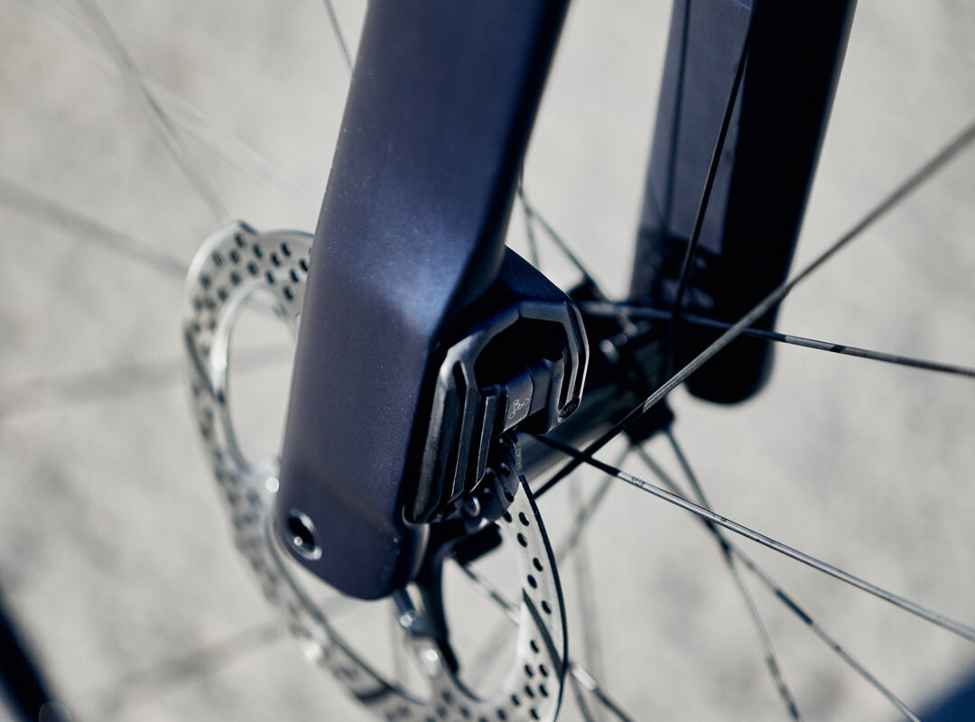
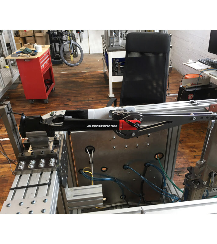
After developing several concept designs, the most successful design moved on to the prototyping phase, with a prototype developed in-house at Argon 18’s R&D lab. In early concepts, half of the caliper was designed directly on the fork leg, the other half was bolted to it. This didn’t allow for the required adjustability of the caliper. The issue was solved by returning to a bolted junction between the caliper and the fork. Rather than having half of the caliper as part of the fork, this design would fully encompass half of the caliper to better integrate it.
The internal mechanics and hydraulics of the caliper were designed in collaboration with TRP, reusing regular internal parts that are used on existing products: piston and seals, for example. Prototypes of this caliper design were then produced.
To allow for testing of these prototypes, a test fork was required. We used an existing Argon 18 fork that was cut on the caliper side and bonded with a custom-made composite fork leg or “sheath”. The sheath included the dropout, the housing and the brake caliper attachments as well as a part of the left fork sheath. The opening in the caliper housing was used to allow fins to pass over the caliper for better cooling. Our prototype in this case used disc brakes with a quick release – while we anticipated the final design of the braking system would be thru-axle, we didn’t find any discrepancy at this point of testing in using the existing, quick-release fork.
While it is a challenge to prototype with composite materials, it was necessary in this case to determine if the heat generated by the brake would be an issue with this design.
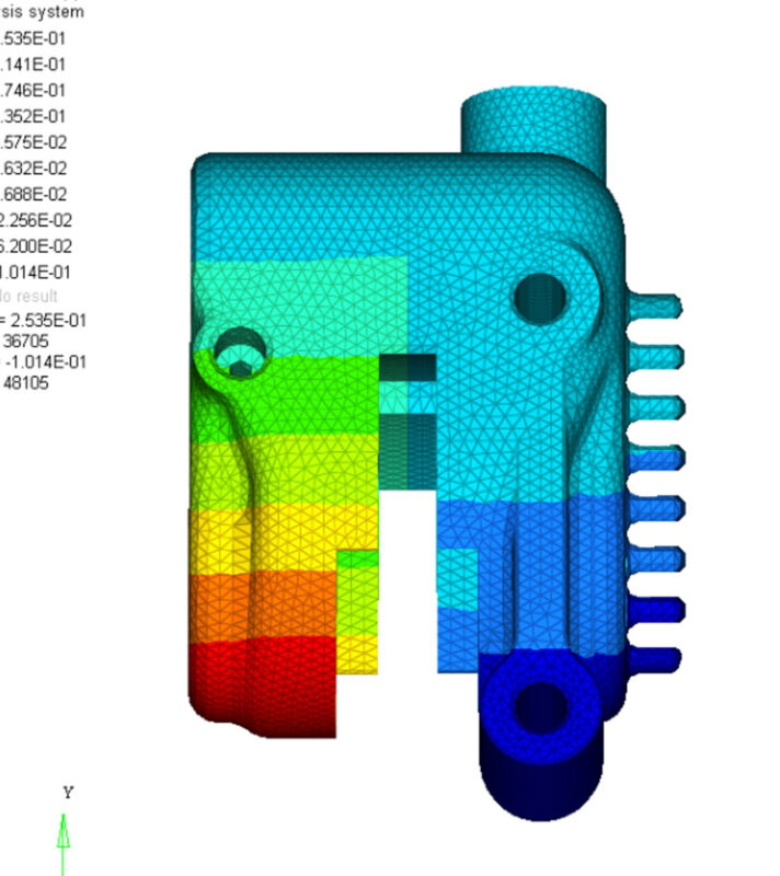
Caliper development – structural integrity
Caliper deformation analyses have been carried out to guarantee the caliper's rigidity under braking (low deformation), which is important to guarantee solid braking performance - and a responsive feel at the lever.
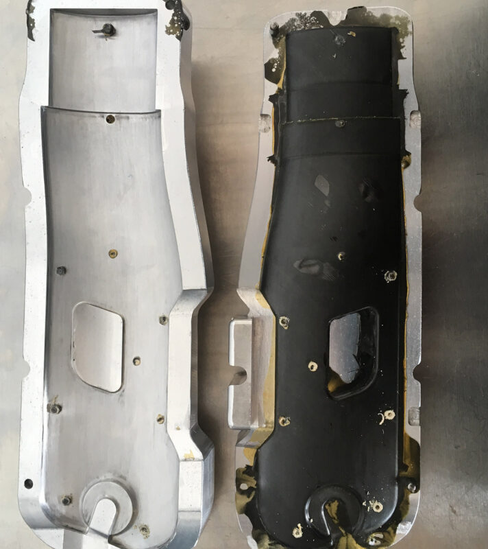
Not only did we design the test fork entirely in-house, we also manufactured it at Argon 18’s headquarters. Our R&D team has a high level of expertise in this in-house prototyping and manufacturing process. The traditional development process requires the machining of a mold in order to manufacture carbon fibre test parts, but in this instance, we knew several design iterations would be needed and wanted to expedite the process. In-house manufacturing skills and equipment allow for this rapid iterative process, to our exact specifications.
The layup was first developed using FEA analysis based on the prepregs available in-house. The ply book was then designed and the prepreg plies drawn, and nested to be cut on the prepreg sheets. The mold to prototype the composite fork leg was first made using a 3D printer. One sample was produced and bonded to a fork, which was then tested in fatigue testing equipment to ensure it would allow for all safety and performance tests.
The existing fork we were using was designed for rim brakes, so required extra reinforcement at the fork crown to withstand the pressure of disc braking. As several fork leg samples were required to make an acceptable test fork, an aluminium mold was machined, being more durable.
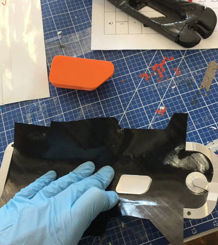
In-house Prototyping and Manufacturing
The entire manufacturing process was carried out at Argon 18, from cutting the materials to finishing and gluing. The manufacturing system was also developed in-house.
Stage 2: ISO and Performance Testing
Once we had a fully realised prototype, we moved onto testing. ISO tests were performed and a data logger was used to record the temperature of the fork, brake pad, caliper and ambient temperature during the test.
ISO testing is composed of two different tests: brake performance followed by heat resistance. Brake performance consists in checking that sufficient braking force and distance can be reached from a controlled force at the brake lever. Heat resistance consists of applying a constant force at the lever and checking that sufficient braking power can be maintained for a given amount of time. The prototype had passed the brake performance test, but not by enough of a margin for our own internal standards – which are above ISO standards.
We found that the brake performance test was influenced by the mechanics of the caliper itself - more precisely, how it deforms under pressure during breaking. Design modifications were recommended for the next design iteration based on measurements on the actual prototype and FEA analyses.
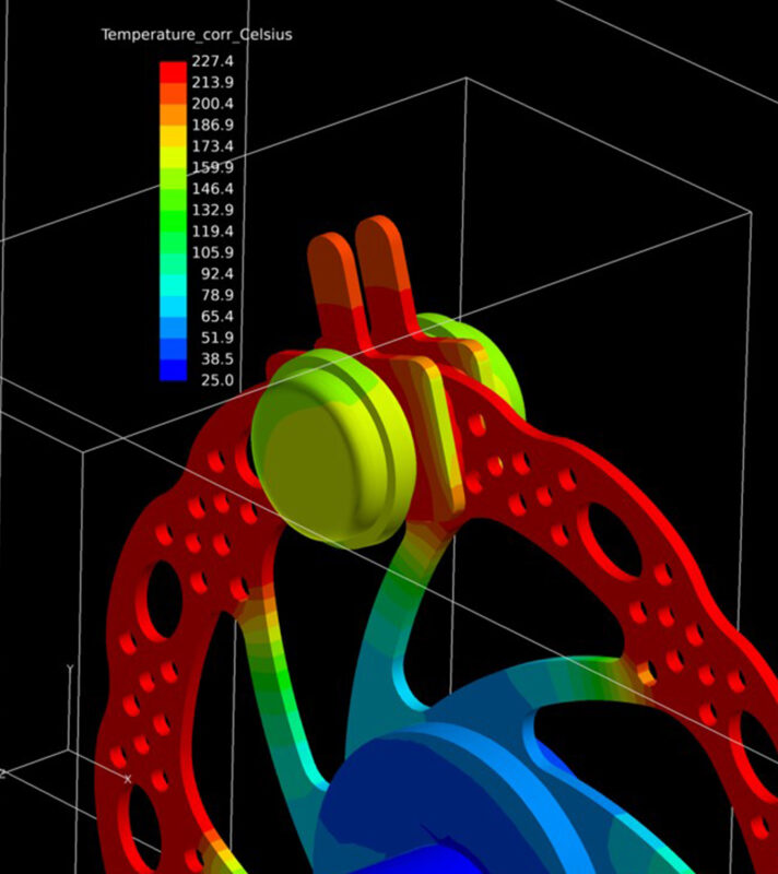
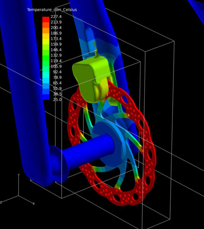
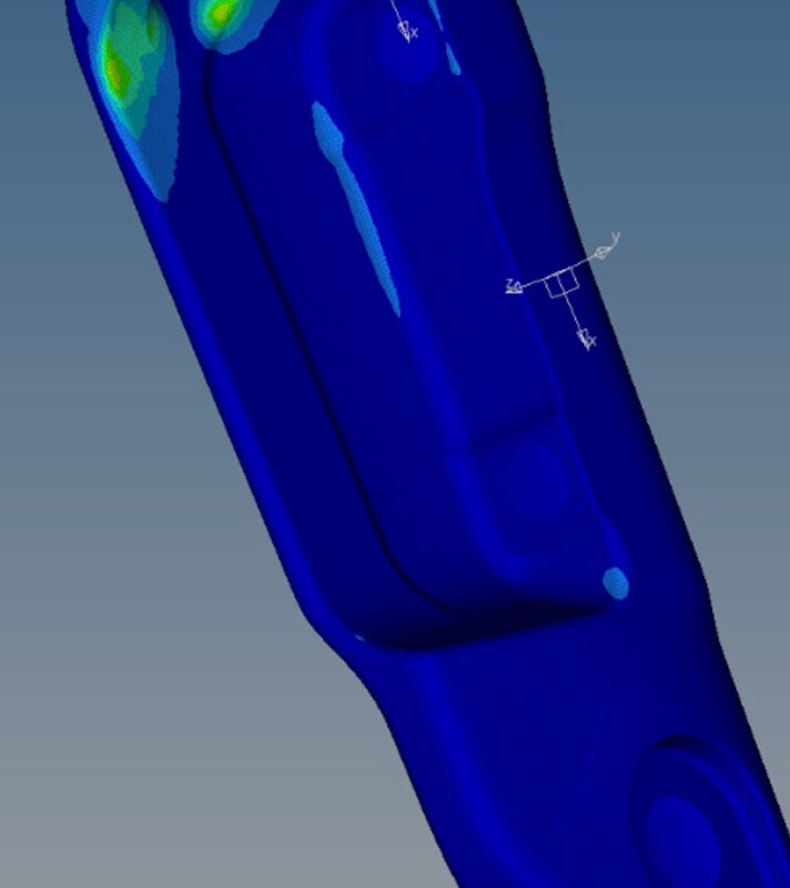
Caliper development - Thermal CFD
These analyses were used in the different phases of development to ensure the best cooling strategy for the calipers and brake pads and to avoid the risk of overheating.
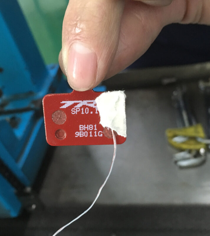
To be sure we were well above thresholds for heat testing, we revised the design of the caliper to limit its opening, and used smaller brake pads. The new design was validated by FEA, and re-tested. This solution included the design of an air duct, a feature that was not present on the first test-run prototype. In our testing process, our results showed that cooling the brake pad was critical, which is why we added the duct. This final design also passed all safety and performance tests.
Our tests found that in normal conditions, the fork reached a maximum temperature of 65°C during the heat resistance test. This temperature poses no concerns in terms of possible heat damage which would cause the composite structure to start to lose its mechanical properties, and passed all ISO test protocols.
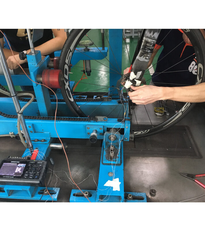
ISO testing of the fork and integrated caliper
Brake fatigue test and data recording of temperatures during the heat resistance test.
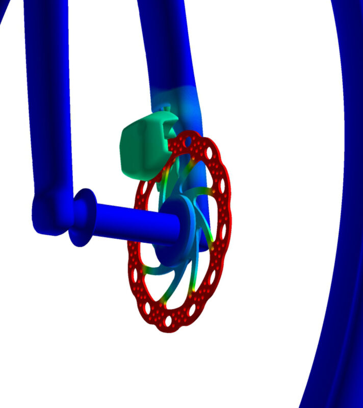
Stage 3: Aerodynamic Evaluation
Of course, we wanted to put our final design to the test, and run a comparison of the aero performance of the integrated disc brake against a standard disc brake. Using CFD analysis on the front caliper we found that the aero improvement of integrated disc brakes versus traditional disc brakes offered a 1W advantage on a flat road for a 300W riding power, or a savings of 10 seconds over 100km on a flat road for a 300W riding power. We also found a 25% decrease of CdA, when looking at the caliper, disc and surrounding fork surface. We'll share more on these results soon, in an upcoming deep dive into aero improvements.
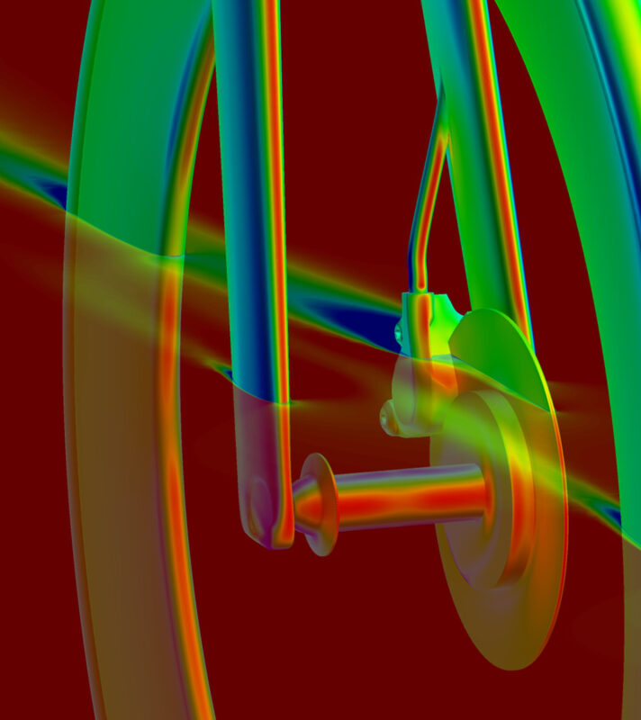
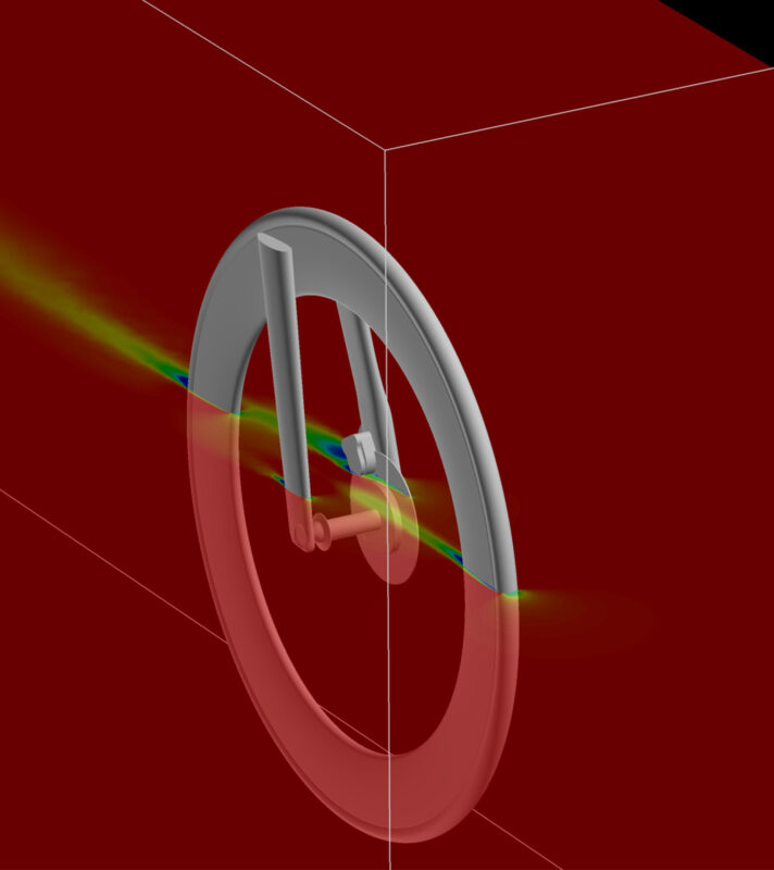
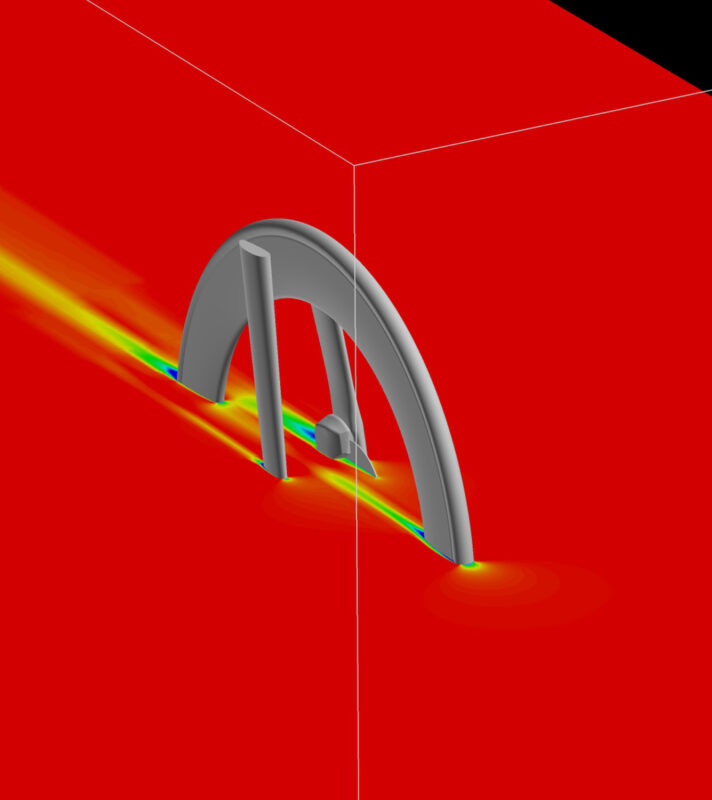
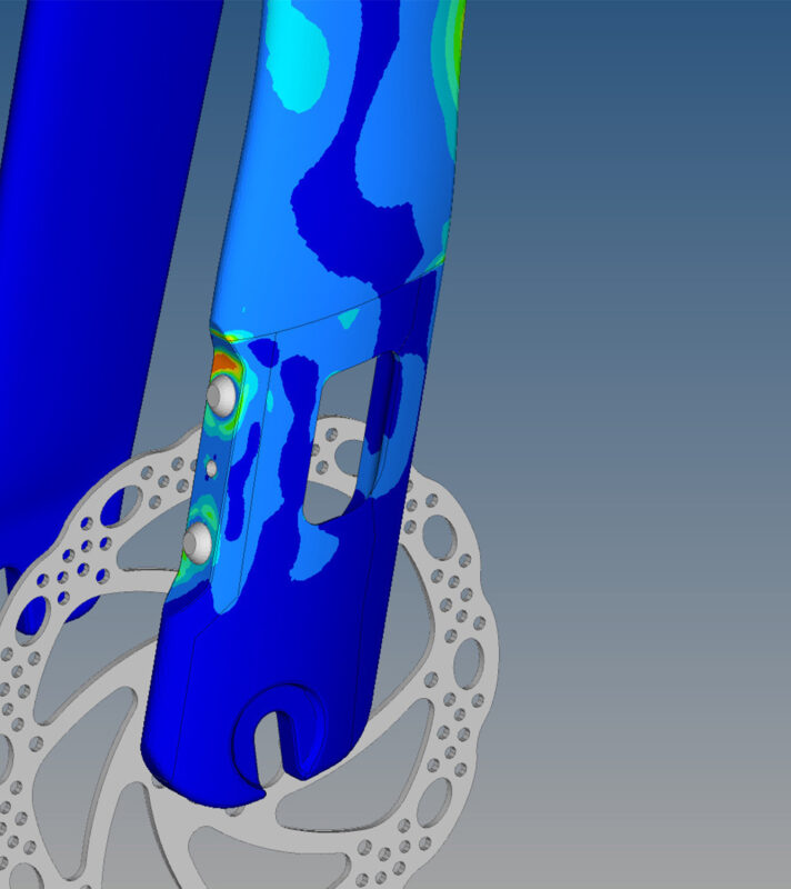
Caliper development - CFD aerodynamical performance
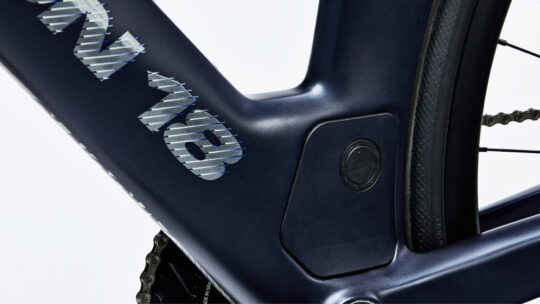
Local evaluations of the effect of the calipers on the aerodynamic performance have been carried out, and while the gains are small, the main gain comes from the fact that the hydraulic sheath disappears. The images show the analyses at the different stages of development.
As we moved forward into production, we also took our prototype to the wind tunnel to validate the design concept – and we’ll be showing those results to you soon.
Stage 4: Production
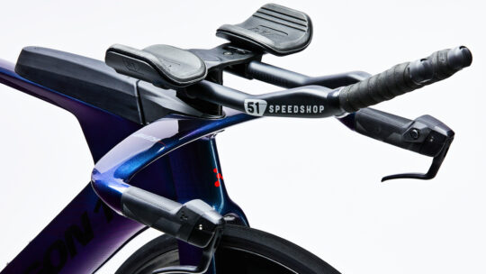
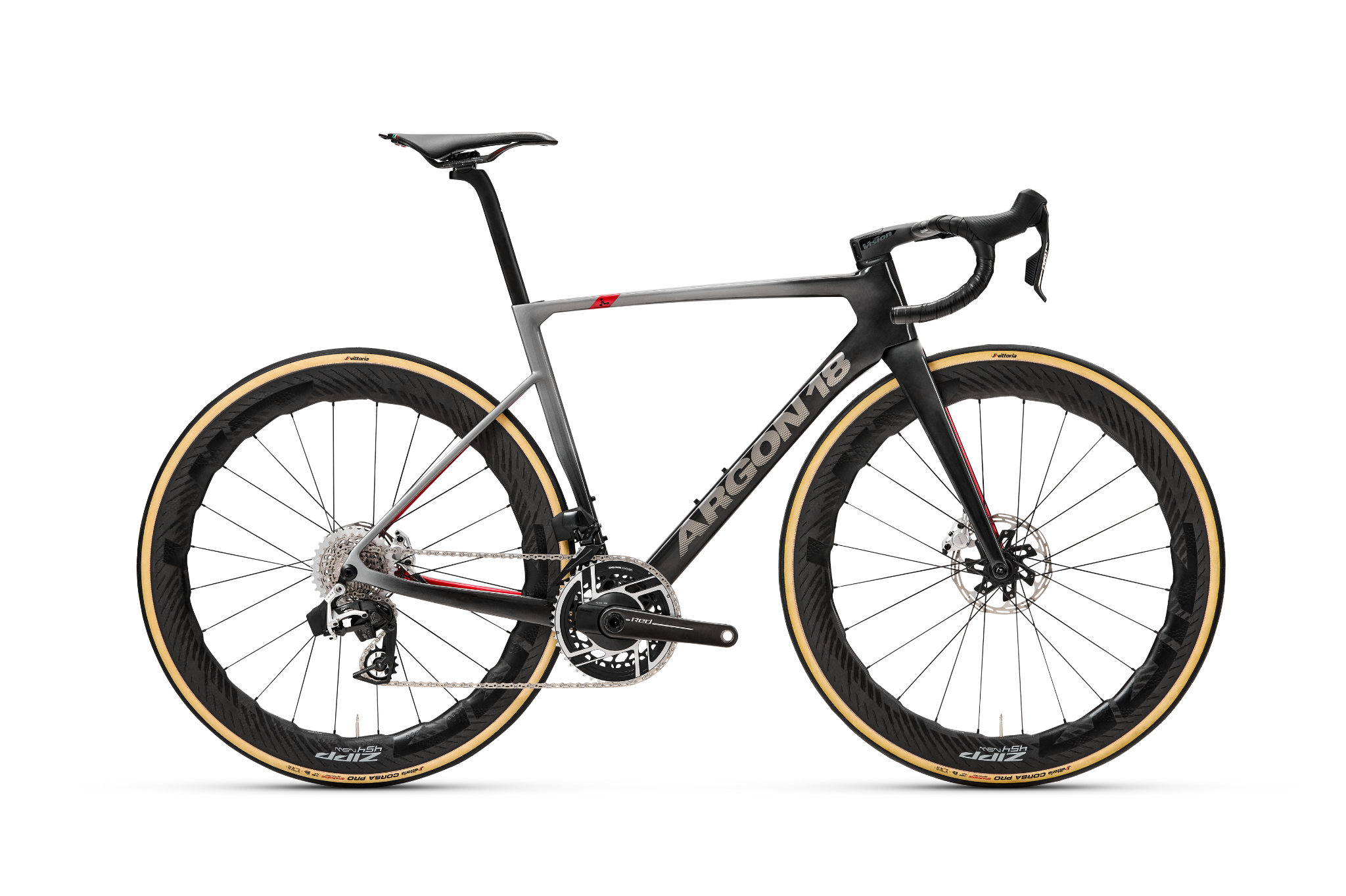
Now you’re probably wondering which lucky Argon 18 bike will the first to feature these brakes… well, it may be our worst kept secret.
To keep up to date, you can subscribe to our newsletter by entering your email below: